Junwei Zhao1, Tobías Felipe2,3, Ruizhu Chen4,1, & Elena Khomenko2,3
1. W. W. Hansen Experimental Physics Laboratory, Stanford University, Stanford, CA 94305-4085, USA
2. Instituto de Astrofísica de Canarias, 38025 La Laguna, Tenerife, Spain
3. Departamento de Astrofísica, Universidad de La Laguna, 38205 La Laguna, Tenerife, Spain
4. Department of Physics, Stanford University, Stanford, CA 94305-4060, USA
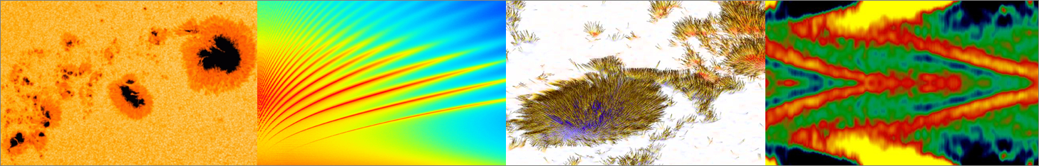
Atmosphere above sunspots is abundant with different types of waves. Among these waves are running penumbral waves in the chromosphere, quasi-periodic oscillations in the lower coronal loops, and recently-reported running waves in sunspots’ photosphere, all of which were interpreted as magnetoacoustic waves by some authors. Are these waves in different atmospheric layers related to each other, what is the nature of these waves, and where are the ultimate sources of these waves? To answer these questions, we select a sunspot inside NOAA AR 11836 and collect high cadence observations of the sunspot from SDO/HMI, SDO/AIA, IRIS, and BBSO/NST. Observations from a total of 16 spectrum lines (or channels), examples of which are shown in Figure 1, are used covering a period of 17:22:30 – 18:05:42UT, 2013 September 2.
Figure 1 | Snapshot images from each of the 16 spectrum lines/channels used in this study, listed in the order of the line-formation height or temperature, from the lowest to highest: (a) HMI Fe I 6173 Å continuum intensity, (b) HMI line-core intensity, (c) AIA 1700 Å, (d) AIA C IV 1600 Å, (e) NST Hα − 0.4 Å, (f) IRIS Mg II k 2796 Å, (g) NST Hα line center, (h) IRIS Si IV 1400 Å, (i) IRIS C II 1335 Å, (j) AIA He II 304 Å, (k) AIA Fe VIII/XXI 131 Å, (l) AIA Fe IX 171 Å, (m) AIA Fe XII/XXIV 193 Å, (n) AIA Fe XIV 211 Å, (o) AIA Fe XVI 335 Å, and (p) AIA Fe XVIII 94 Å. Panel (a) also shows our measurement scheme. Location “O” is the approximate center of the sunspot, “A” is a reference point, and the red line indicates the sunspot’s radial direction passing location “A”. The white circles delineate where reference points are selected for an azimuthal average.
We use cross-correlation calculation, a method used in typical time-distance helioseismology, to establish connections between waves at different atmospheric levels and to trace the propagation of these waves. A similar analysis procedure was used to trace solar p-mode waves from the photosphere into the solar interior using numerical simulation data1. The analysis procedure is as follows. As shown in Figure 1a, a point “A” near the umbra and penumbra boundary at the bottom layer is selected as a reference point. The time sequence at “A” is then cross-correlated with time sequences taken at all locations along the red line on all layers. For each layer we obtain a time-distance diagram, which stacks all cross-correlation functions for each horizontal distance.
Figure 2 | Time–distance diagrams, showing cross-correlation functions between the HMI Ic images and images of all available wavelengths or channels, displayed in the same order of line-formation heights as in Figure 1. Point “A” in panel (a) represents the location “A” in Figure 1(a), at a horizontal distance of 5Mm and time lag of 0 minute. Horizontal distances are relative to the sunspot center, and relative travel times can be positive and negative.
Figure 2 shows these time-distance diagrams for all 16 layers. A clear wave feature is seen in all diagrams except in panel (p) correpsonding to 94Å data, and this indicates that part of the waves in the upper atmosphere originate from the photosphere. The time lag in the diagrams are relative to when the wave passes the location “A” at the horizontal distance of 5 Mm.
Figure 3 | Cross-correlation functions after stacking together based on line-formation heights, displayed for selected time lags. The left panels are for the 6–7 mHz band wave, and the right panels for the 3–4 mHz band. Note that the selected time lags are different in the left and right panels. The white lines in the two middle panels represent the potential magnetic field lines extrapolated from the photospheric field. Location “A” is marked at τ = 0 s for both frequency bands. Approximate atmospheric layers, photosphere (Ph), chromosphere (Ch), transition region (TR), and corona (Co) are marked as atmospheric heights, but these approximations are based on the line formation in quiet regions.
Following the practice given in Ref.1, in order to show the vertical structure and propagation of the wave feature, we stack these time–distance diagrams based on their relative heights to obtain a three-dimensional function, with horizontal distance and height as the first two dimensions and time lag as the third dimension. The third dimension is then decomposed into different frequency bands. Figure 3 shows the picture of how waves channel upward for 3-4 mHz and 6-7 mHz bands. The 6–7 mHz wavefront forms an inclined line and moves slantingly upward, possibly along magnetic field lines. The wave at this frequency does not seem to get cut off below the corona and can make it to the corona even in the areas with nearly vertical magnetic field (see τ = 72 s in Figure 3a). For 3–4 mHz, the wavefront appears farther away from the sunspot center at the beginning phase of the wave propagation and forms a different shape compared with the wavefront of 6–7 mHz. At the early phase, such as τ = 0 and 48 s, the wavefront shows a shape of backward-“C,” most protruding outward in the lower chromosphere. As time evolves, the wavefront in the photosphere and corona moves faster than in the chromosphere and transition region, distorting the shape of the wavefront to an “S”-shape at τ = 96 and 144 s.
Where do these upward-channeling waves initially originate? Based on a previous study (Ref. 2) and numerical simulations as shown in Ref. 3 and 4, we estimate that these waves are likely excited about 5 megameters beneath the sunspots’ surface, although it is not clear what excites these waves.
For more details of this work, please refer to a recent publication Ref. 4.
References
[1] Zhao, J., Georgobiani, D., Kosovichev, A. G., Benson, D., Stein, R. F., & Nordlund, Å. 2007, ApJ, 659, 848
[2] Zhao, J., Chen, R., Hartlep, T., & Kosovichev, A. G. 2015, ApJ Lett., 809, L15
[3] Santamaria, I. C., Khomenko, E., & Collados, M. 2015, A&A, 577, A70
[4] Zhao, J., Felipe, T., Chen, R., & Khomenko, E. 2016, ApJ Lett., 830, L17