Sebastien Couvidat and Rock Bush
W. W. Hansen Experimental Physics Laboratory, Stanford University, Stanford, CA 94305-4085
Surprising as it may be, the solar radius is not known with an extreme accuracy. In fact, Ref. 1 cited a 500 km difference in the results of various studies.Using ground-based observatories, it is difficult to reach a high precision as the Earth atmosphere impacts image quality. Space-based instruments, like the Michelson Doppler Imager (MDI) onboard SoHO and its successor the Helioseismic and Magnetic Imager (HMI) onboard SDO, provide much better quality images that can be used to accurately measure the solar radius. Unfortunately, some of these instruments’ characteristics may not be well known either: e.g., their plate scale may have an associated uncertainty that is too large for an accurate solar radius measurement.
Once in a while though, the solar system provides an helping hand in the form of planetary transits. Celestial mechanics is known to such a high degree of precision that exact timing of a transit is very well known. Therefore, transits can be used to improve the knowledge of the plate scale of instruments like HMI, but also to accurately determine the solar radius at the specific instrumental wavelength. The basic idea is to time the instant at which the planet enters (ingression) and exits (egression) the solar disk. A comparison between the measured transit duration and the duration predicted by ephemeris as a function of the solar radius returns the exact value of this radius.
On June 5, 2012, Venus crossed the solar disk. Venus transits are fairly rare events. They usually happen by a group of two, eight years apart, with a repetition pattern of 121.5 yrs and 105.5 yrs. The previous one happened on June 8, 2004, and the next one is expected in 2117. During the transit of 2012, the HMI side camera took true continuum images at a cadence of 3.75s in linear polarization (in Stokes parameter terms, the sequence was I+Q, I-Q, I+U, and I-U). Here, only the level-1 images from the side camera have been used.
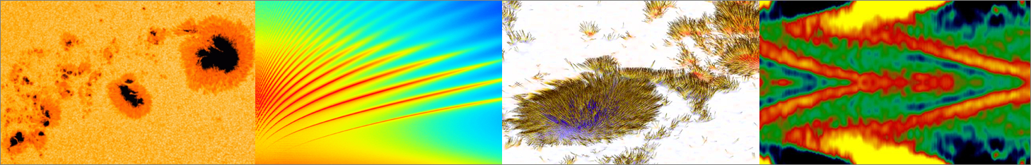
Figure 1 | Processed HMI image of the solar disk with Venus crossing the limb (in orange) during ingression.
These images have been flat fielded, had the dark frame and CCD bias removed, as well as the overscan rows and columns, as part of the standard level-1 pipeline processing. Furthermore, the instrumental distortion has been corrected, based on Ref. 2. An estimate of the point-spread function (PSF) of HMI is also used (provided by Aimee Norton). This PSF is deconvolved from the images using an implementation of the Richardson-Lucy algorithm (written by Mark Cheung). Once all the 816 images used for the analysis have been processed, the standard HMI limb finder is run on each one to locate the solar disk center and the solar limb (defined as the inflection point of the limb darkening function — LDF —). Two background images obtained by averaging 80 images prior to ingression, and 80 after egression, are computed. Each Venus-transit image is divided by the appropriate background.On each image, we measure the surface area of Venus inside the solar disk (Figure 1): this is the number of pixels with an intensity below a given threshold and located inside the solar disk as defined by the inflection point of the LDF. Venus is deemed to cross the solar disk when about half of its surface area is inside the disk. The exact number is actually smaller than half because of the Sun’s curvature (it can be easily derived from the formula of circle-circle intersection). Finally a polynomial fit of the surface area of Venus as a function of time is made to accurately determine the exact contact time (Figure 2).
Figure 2 | Surface area (in pixels) of Venus inside the solar disk during ingression (upper panel) and egression (lower panel), minus the expected surface area at the time of contact between the center of Venus and the solar limb. In red is shown the polynomial fit that is used to precisely determine contact times.
The result we obtain is a solar radius of 959.58″ at 1 AU, again for a radius defined as the inflection point of the LDF. This radius is smaller than the 960.12″ obtained from MDI data during Mercury transits1, and it will be interesting to understand the origin of this difference. The most difficult part here is to assign an error bar to our estimate. Indeed, the literature abounds with radius estimates differing by much more than their error bars. A reason is that, often, only statistical error bars are provided. Here we focus on systematic errors, which we believe are significantly larger than statistical ones. We computed the difference between solar radii obtained with and without PSF and instrumental distortion removed, with different intensity thresholds (this matters because of the atmosphere of Venus), with different orders of the polynomial fit to obtain transit times, etc. By adding quadratically these values, a total uncertainty of 0.27″ is obtained (at 1 AU). This value is a lower limit on the actual error bar, because there are systematic errors that we have ignored and/or cannot be estimated.
References:
[1] Emilio, M., Kuhn, J. R., Bush, R. I., and Scholl, I. F., 2012, ApJ , 750, 135
[2] Wachter, R., Schou, J., Rabello-Soares, M. C., Miles, J. W., Duvall, T. L., and Bush, R. I., 2012, Sol. Phys., 275, 261
959.58″ at 1 AU corresponds to a radius of 695.96 Mm, i.e. slightly less than the 696 Mm often used as a reference in stellar evolution codes that compute 1D solar models.
How many megameters is your measured radius? I know I can convert arcsec into megameter myself, but it’s good to post your answer here for other readers.