Pascal Saint-Hilaire1, Jesper Schou2, Juan-Carlos Martínez Oliveros1, Hugh S. Hudson1,3, Säm Krucker1,4, Hazel Bain1, Sébastien Couvidat5
1 Space Sciences Laboratory, University of California, Berkeley, CA, USA;
2 Max-Planck-Institut für Sonnensystemforschung, Justus-von-Liebig-Weg 3, 37077 Göttingen, Germany;
3 School of Physics and Astronomy, University of Glasgow, Glasgow, UK;
4 University of Applied Sciences and Arts Northwestern Switzerland, CH-5210 Windisch, Switzerland;
5 W.W. Hansen Experimental Physics Laboratory, Stanford University, Stanford, CA, USA
Observations
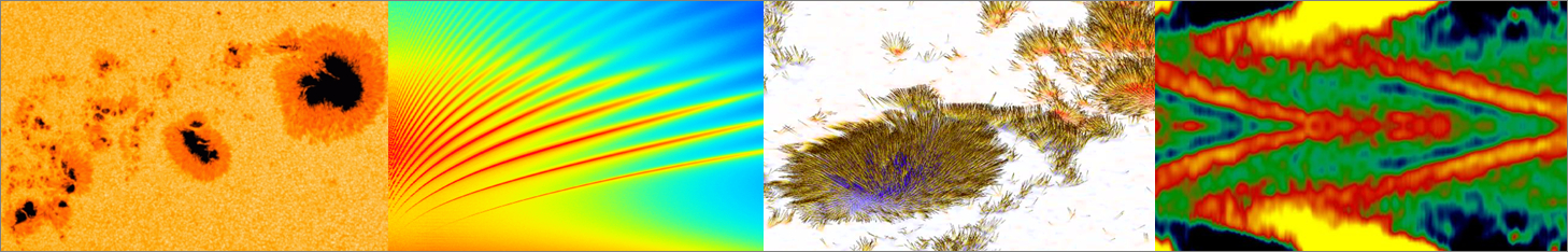
Figure 1 is a reproduction of Nugget #9’s Figure 3, showing the loop system of the 2013 May 13 limb flare at different wavelengths.
Figure 1 | The gradual-phase sources, with image times: 16:25:22.7 (WL), 16:25:28.1 (160 nm), and 16:25:21.5 (19.3 nm). The AIA 19.3 nm EUV image shows loop-shaped absorption features, corresponding loosely to the WL and UV loops. The purple contours are from RHESSI observations of thermal X-rays, and the red line is the 20% contour level of the HMI image.
Figure 2 | 2013 May 13 GOES X-ray (black: 1-8 Å orange: 0.5-4 Å) and HMI Stokes I, Q, U, V time profiles. The HMI lightcurves are generated by averaging over all six filters the pixels in the green box of Figure 1. Each pixel within the box was temporally median-filtered (with window size 3). No other data alterations were performed.
Figure 2 displays the 24-hrs GOES X-ray lightcurves, as well as HMI Stokes parameters accumulated over the green box in Figure 1 (leftmost plot). On top of slowly-varying components (due to instrumental and other effects), a clear flare signature is observed. Note that HMI has six narrow-band filters near the 6173 Fe I line that were averaged for improved signal-to-noise, but all quanlitatively display the same profiles after background-subtraction. Moreover, in the following, the original Stokes Q and U have been rotated into another frame (Q’,U’), where +Q’ is the horizontal component.
Figure 3 displays Stokes I and Q’ or Q’/I for two different regions of interest: A (HMI loop leading edge) and B (material higher up in the corona, visible later in the event). Both display high degrees of linear polarization (respectively, ~13% and ~20%), very close to the levels expected from pure Thomson scattering of free electrons at these different altitudes and wavelengths (respectively, about 15 and 21%). When the brightest part of the loop reaches region A, the level of linear polarization drops to about 3%.
Figure 3 | Left column: 4.5 minute average Stokes I (top left) and Stokes Q’/I (bottom left) centered on 16:16:41 UT. Right column: average from 16:03 to 18:23 UT of Stokes I (top right) and Stokes Q’ (bottom right) fluxes. The images are averages from all six HMI filters, with pre-flare images subtracted in the case of Stokes I images. To improve SNR, all images were rebinned to 4” pixels from the original 0.5″ pixels. The green contours in the images on the left correspond to the 4, 8, 16, and 24 DN/pixel levels of the 0.5″ Stokes I image. For clarity, with pixels whose Stokes I values were below 4 DN/pixel put to zero in the Stokes Q’/I image, the areas below the photospheric limb were also displayed as black (and 5″ higher for the bottom images).
Discussion
Assuming that Thomson scattering is the sole source of linear polarization, the mass associated with the polarized component can be computed, and found to be 8.2×10¹⁴ g, about half that of an “average” CME. The free electron density of the white-light loop was possibly as high as 1.8×1012 cm-3, assuming unity filling factor. RHESSI X-rays, which can diagnose hot (>8 MK) free electrons, finds densities of the same order. A full spatio-temporal comparison between these two instruments is in the works.
What about the unpolarized component, when the loop rising through Region A is at its brightest? As can be seen in Figure 1, the WL/UV loop tends to transform into an obscuring feature in EUV. This supports the idea that this plasma is relatively cold (< 100 kK or even lower). Such a plasma would be unobservable in X-rays, and probably unobservable to radio observations also, due to optical thickness. Thermal (free-free + free-bound) radiation seems a likely source for the unpolarized bright component, though some emission by neutral Fe I (that would have to be Doppler-shifted by the turbulent loop plasma into a near-continuum) is a possibility. These open questions are being actively investigated, with the objective being to derive a new important and reliable diagnostic tool for solar limb flare research.